Posted on Leave a comment

AquaCure AC50 Purchasers NEED to KNOW

Congratulations on this step to better health.

This eMail is needed to tell you things that are VITAL to your ownership, startup, use and enjoyment of the AquaCure AC50  PLEASE read ALL this eMail!

First VITAL:  Your Eagle-Research User Account…
When you purchased your AquaCure, if you didn’t already have one, the website automatically created an account for you (usually based on  the eMail you used to order) and sent you the account details (including the password).  This is NEEDED to access your online Resources.

If you did not receive the password eMail, check your junk or spam folders and if it’s there, drag it into your inbox, to whitelist us.  The internet is NOT KIND to our eMails…

If you cannot find the eMail, you can still get into your user-account by using the ‘lost password’ procedure.
https://eagle-research.com/my-account/edit-account/

Then you can change the password to whoever you want and Very Important… Press UPDATE at the bottom of the page to tell the website to remember your changes.

If you DON’T receive the ‘lost password reset’ eMail (sent to the eMail address you used to purchase the AquaCure), then your eMail SERVER (Hotmail, gmail, yahoo, etc.) is deleting the automatic eMails from our website before they get to you.
Nothing I can do about that.
But YOU should be able to talk to whomever is serving your eMails and tell them to whitelist
website_emails@mg.eagle-research.com

NOTE: Since you purchased the AquaCure from us directly, your AquaCure IS REGISTERED and your Satisfaction Guarantee and Lifetime Warranty are started.

There are things that we cannot say online (AquaCure Sales Page) or organizations like customs or the FDA will not deliver the AquaCure to you and/or shut us down.

The issue is that the AquaCure is not registered as a ‘Medical Device’ AND we are not Doctors (as certified by Big Pharma indoctrination) thus we cannot make any claims or even imply that it can be used for Human ailments.
https://eagle-research.com/legal-medical-disclaimer/

We ARE working to get certification (we are paying for appropriate scientific studies), but the process is time consuming (will take years) and expensive (might take millions of dollars) even if they do approve it in the end.  And they might not…

Because products that do what the AquaCure can do (virtually eliminate most of the drugs big Pharma sells) are treated with extreme prejudice… Where products that harm people are often immediately approved, at Warp Speed and without appropriate safety testing… Such is the upside down world we now live in…

So HERE, in a personal eMail to YOU, we will tell you what you need to know and we invite you to ask questions if needed.  But do please read review the links below first and then be specific with your questions, our people are working hard to help everyone.

First to know, the AquaCure AC50 Operation Manual is NOT INCLUDED in the AquaCure box (because it contains details for human use of the AquaCure).  You can download the current Operation Manual Here
https://eagle-research.com/wp-content/uploads/2019/08/AC50-Operation-Manual190414.pdf

What is included in the AquaCure box is a ’throwaway’ instructions pamphlet (from the original VING chassis) on how to setup to fuel a MICRO-TORCH…
Which the AquaCure CAN do and will be needed to apply protocols 5 and 6 (DDW and New Water).
Use as a micro-torch is 100% LEGAL and what you would say if anyone calls you and asks what your ‘end use’ is…

The micro-torch is not included ‘just for show’… In addition to the great fun you can have using the micro-flame, it has EXTREME VALUE for HEALTH.  And we will tell you about protocols 5 and 6 when we get current projects taken care of.
Again, subscribe to our eNews for notification when we are ready.

Because the AquaCure AC50 developed (upgraded) faster than the instructions, here is the Operation Manual UPDATE, which has information that supersedes the Manual
https://eagle-research.com/wp-content/uploads/2021/11/AquaCure-Operation-Manual-Update-Notes.pdf

Our intention is that you print the Operation Manual and Update for yourself.
If you wish to purchase a paper copy of these Operation instructions, you can buy them from:
https://eagle-research.com/product/aquacure-operation-manual/
And they will be shipped separately from the AquaCure Box.

We ARE making an amazing, new and professionally done, AquaCure AC50 Assembly and Operation Manual, that will replace the above once done.
Subscribe to our eNews to be informed when it is ready.

NEXT (NOT included in the Box) is the Nasal Cannulas.  Those are a dead giveaway that the AquaCure in the box is intended to be used for Humans.  ‘They’ occasionally open the boxes enroute, and examine the contents, so we need to be careful what is IN the box.  We cannot have cannulas in the box

So, there are MANY places you can purchase nasal cannulas online and get them very fast.
For example:
https://www.amazon.com/s?k=nasal+cannula+adult+soft+touch+7%27+tubing&crid=OLNCYOEO4W3G&sprefix=nassal+cann%2Caps%2C90&ref=nb_sb_ss_ts-doa-p_10_11

If you wish to purchase cannulas from us, we sell them here:
https://eagle-research.com/product/nasal-cannulas/
and they are SHIPPED SEPARATELY from the AquaCure Box

Click here to see an impromptu AquaCure AC50 Setup and Operation Video.
https://youtu.be/723gzax3z7Y
We ARE making better (professionally done) videos and those will be available to you once done.
Subscribe to our eNews to be informed when they are ready.

THIRDLye IS usually included in the box, but sometimes customs removes it (it’s a white powder) so we cannot guarantee that it will arrive.
Again, lye is easy to buy online, for example:
https://www.amazon.com/Lye/s?k=Lye

AquaCure New Timer Switch
https://youtu.be/P0J4GxuddxM

Apply Teflon Tape on AquaCure Fill Stem
https://youtu.be/sFXJaOSwwZs

Properly Install the Tower Cap
https://youtu.be/Pr98DMe94No

Make sure your Tower Cap base Union is sealed properly (it may take up to 30 wraps of Teflon Tape and that (in the future) you remove the Tower Cap using the Union ring (no need to remove the Union base), so you do not need to keep re-applying the Teflon Tape.
DO NOT ’torque’ (twist) on the Tower Cap itself to seal the Union base fitting; doing so will ‘lock up’ the big Union ring, requiring wrenches to loosen it.
ALWAYS install the Union base FIRST (look for the white box), THEN put the Tower Cap on the base.
A band wrench is now included to help you tighten the Union base onto the Fill stem.

AquaCure Rinsing Technique
https://youtu.be/oac55WgfIvs

When Rinsing:
To dissolve soap formations and lye crystals you need water in the 120° F to 140°F range.  The water must be hot; warm water does little.

Remember to trade out the hot water within a minute or so (at first) because it will cool quickly as it heats up the components.
You Fill the AquaCure to FULL with HOT water (6 to 7 cups).  Then alternately and SLOWLY lift the front and back of the machine up to 60 degrees to ‘wash’ the HOT water up and down in the Sight Tube.
You need to change out the HOT water frequently because it cools off quickly and warm water does little to dissolve soap.
NOTE: If the HOT water doesn’t ‘’reach’ the tight tube, doesn’t wash’ up and down in the sight tube, it CANNOT clean the sight tube; if you are not getting the water washing up and down in the sight tube, it’s likely due to a plug or restriction that needs to be fixed ‘manually’; ask for instructions.

Note: I occasionally get an ‘air bubble’ in the tube (so it will seem that the sight tube and/or ball is not ‘registering’ the actual fluid level correctly).
Generally air bubbles will eventually clear on their own, but you can ‘hurry’ the process by filling the AquaCure with solution.  Then alternately and VERY SLOWLY lift the front and back of the machine up to 60 degrees to ‘wash’ the solution up and down in the Sight Tube, washing out the air bubble(s) and then the ball should float properly.

H2 Hubb AquaCure AC50,  Unboxing, Setup and Test videos:
Unboxing   https://www.youtube.com/watch?v=i5CAuVYu_a4&t=368s
Setup    https://www.youtube.com/watch?v=PAmDyKdai4Y
Test gas production   https://www.youtube.com/watch?v=w1GOztHEOgk

Optionally: Setup your AquaCureAC50 torch attachment:
https://youtu.be/v2ufQWJ0l0Q

See Brown’s Gas testimonials / studies / etc. here:
http://eagle-research.life

AquaCure Brochure
https://eagle-research.com/wp-content/uploads/2020/02/AC-Brochure-small-v4generic.pdf

Brown’s Gas for Health (legacy page)
https://eagle-research.com/browns-gas-for-health

What is Brown’s Gas?
https://eagle-research.com/q-what-is-browns-gas-bg/

Why would you want Brown’s Gas in your life?

https://eagle-research.com/why-does-browns-gas-supplementation-help-health/

Why is Brown’s Gas better than pure hydrogen?
https://www.youtube.com/watch?v=amruwdyj3j0

I cannot legally tell you how to use your AquaCure for health (that’d be ‘prescribing’) but I can tell you how I use it
https://eagle-research.com/how-i-use-browns-gas-for-health-enhancement/

Plants Don’t Lie
https://eagle-research.com/plants-dont-lie/

Purchase your AquaCure model AC50 here:
https://eagle-research.com/product/ac50/

May the blessings be
🦅George Wiseman

Posted on Leave a comment

Free Energy Already EXISTS! It is simply suppressed…

Re: Weigh In: America’s Oil Dependence as per OurEnergyPolicy.org
To Bill Squadron,

Gary Vesperman asked me to add my comment to your energy policy presentation.

I’m very surprised that Gary Vesperman, of all people, hasn’t addressed the elephant in the room.

He is one of the few people I know that has been gathering evidence about the suppression of energy innovation in America specifically and around the world generally.

I did not see anything in the discussions or comments that actually addresses the REAL problem…

Capitalistic Politics (aka Vested Interest Control).

It is a FACT that there are many practical technologies already proven and existing that could solve our energy problems in a very short time, at minimal cost.  It’d also put a LOT of people to work.
This includes both interim technologies (to assist phase-over) and long term eco-compatible technologies.

We could be 100% energy independent for a fraction of the military cost of ‘maintaining’ present fossil fuel policy and infrastructure.  We’d also stop making enemies faster than we can kill them.  How much blood are we willing to exchange for oil?  Will it stop when it’s OUR blood being spilled?

I personally have several fuel saving technologies (in use since 1984) (click) that could cut the use of fossil fuel by 50%, with a payback time between 6 months and 5 years depending on the application; this is assuming that people retrofit the technology… it would be MUCH less expensive (and potentially more efficient) to simply incorporate it OEM.

There are over 5000 fuel-saver patents that are NOT incorporated into any vehicle.   Nearly a hundred years ago Charles Nelson Pogue invented a carburetor that would take an ordinary 4 door car over 200 mpg with perfect power and pretty much zero pollution.

There is no question in my mind that, with publicly EXISTING technologies, the USA could reduce oil imports to accept oil only from ‘friendly’ countries (like Canada and Mexico) within a couple of years and be totally oil independent within 5 years; just with fuel-saving technologies that I know are practical and inexpensive.
(Cutting down the military use of oil would be a tremendous help).

I have several other energy saving technologies too, like my capacitive power supply (that could be incorporated into smart-grids and appliances).  I’m no genius (as my wife can attest), I developed all of this with only the resources available to the average homeowner and using technology available nearly 100 years ago.

I have felt the sharp edge of Vested Interest suppression…
I have many stories about that (click)

I believe:
Talk (and presentations) about energy policy won’t change anything until suppression is removed.
NO progress will happen as long as government energy policy is influenced by Vested Interest.
NO progress will happen as long as Vested Interest is allowed to directly suppress innovators.

The government itself is one of the Vested Interest, receiving up to $0.70 of every fossil-fuel dollar via various taxes (starting with wellhead tax and including income tax from industry employees).

Most people think it is some wild “conspiracy theory” if anyone claims that the government has ever prevented an invention from coming to market. If you are willing to explore the idea, WIRED magazine just published a story on this topic that you can read here:
http://www.wired.com/threatlevel/2013/04/gov-secrecy-orders-on-patents/
As it turns out, any potentially “disruptive” technology will be evaluated for its “national security” impact (I wonder by whom? And by what criteria?) and dealt with accordingly.  The suppressed technology is usually stored in Government archives…

Virtually all energy policy is more political than practical and what is practical is ignored or bypassed (for example: car companies receive minor fines for not meeting fuel efficiency mandates or they bypass the law by creating an entirely new class of automobile like SUV).

REAL energy-saving and energy-producing technologies have been suppressed for over a century.
The government has, hidden in secret, several free-energy and anti-gravity technologies, withheld from the public under guise of National Security.
Just release them and our fossil-fuel issues are over.  Bring the military home to help re-build America.  Help the world and rebuild our reputation.
But none of this will happen as long as Vested Interest controls the government.

Capitalistic Politics, supporting the Vested Interest, is like a Cancer in our Republic.  I think it has metastasized, adding Capitalistic Socialism, which encourages entitlement mentality and is skewed to allow the rich to get richer at the expense of the public, with the government taking ALL of the risk.

Solve Capitalistic Politics in a way that releases the innovative capability of the American People and we’ll automatically solve the energy crisis.
American innovators have ALREADY solved the problem many times and in many ways; and every real answer has been suppressed!

Any ‘energy policy’ discussion that doesn’t first address Capitalistic Politics is, in my opinion, futile.
That’s why I take my innovations directly to the people.

Solve Capitalistic Socialism (stop government from ‘taking care of us’ for the profit of Vested Interest) and we’ll regain the Constitutional rights and freedoms that made us great.  We’ll also regain the essential element of being allowed to FAIL.

I appreciate that some very smart people are trying to address the USA energy policy and I think they’ll come up with lots of good ideas… but I firmly believe nothing presented to the government will succeed in any meaningful way unless the issue of Vested Interest is addressed first.

An extremely focused example is: President Obama won’t put the solar panels back onto the roof of the Whitehouse.  President Carter put them there and President Reagan removed them.  This is a simple and clear indication of the past and present administration’s agenda and intentions.

Making presentations to the fox in control of the henhouse is a waste of energy; bad energy policy in my opinion.

This is the elephant in the room.

May the blessings be?

George Wiseman

Posted on Leave a comment

An OverUnity Formula?

I recently (November 2014) had an interesting (to me anyway) thought while contemplating the Water Powered Generator concept I notified my eNews subscribers about in our enews and a blog update on the old site.

There may be a way to mathmatically ‘prove’ and optimize many over-unity and/or free energy (OU FE) technologies with a simple formula taught in high school physics class.

I’ve noticed a common denominator of many of the OU FE technologies is speed or velocity.

If we use the formula KE = 1/2M*V2,
Kinetic Energy equals one half Mass times Velocity Squared;
we find that velocity is vitally important to efficiently getting energy out of a system.

Let’s take examples of a weight of 10 lbs rising 1 foot and a 1 lb weight rising 10 feet.
Both have done 10 ft/lbs of ‘work’.

Now assume both happened in 1 second.

The KE of the first would be (10/2)*(1*1) = 5

The KE of the second (lighter but faster weight) would be (1/2)*(10*10) = 50

The KE of the lighter faster weight is 10x more than the larger slower weight, even though the ‘work’ done was identical!

Take oxidation as another example:  If iron oxidizes slowly, we call it rust and there is little way to extract energy from it.  If it oxidizes faster, we call it burning and it is hot enough for us to convert some of the heat energy to kinetic energy.  If it oxidizes even faster, we call it an explosion (mix with aluminum to make thermite) and conversion of potential chemical energies to kinetic energy is even more efficient.

With gasoline, we average 3 BTU per combustion event in an internal combustion engine.  If we used 3 BTU of dynamite, the piston would be blown through the bottom of the engine.  The amount of thermal energy (3 BTU) is exactly the same.  The difference is the speed of combustion.
This is why the Bourke Engine was/is so efficient, it is designed to operate with fuel that detonates.
BTW, the safe way to dispose of old dynamite is to burn it in a fire; it doesn’t explode when burned, it just burns like a log.

So, my point is that, technologies using velocity as part of their energy conversion system make use of the part of the KE equation that is velocity squared.

You only consider 1/2 mass, and you square velocity; so moving mass isn’t as effective as increasing velocity.
As the velocity increases, the KE increases squared.  If you are looking for OU FE, (or even just high efficiency) you need to pay attention to velocity.

Back to the so called Water Powered Generator.  While this generator isn’t really water powered (no combustion of water), it does use water as the medium to convert pressure to velocity.
So MAYBE… If the technology is valid, or at least for this theory / concept to be valid… We could work out the energy it takes to pump small amounts of water to high pressure compared to the energy we get back from releasing that pressurized water through a nozzle designed to convert pressure to the highest velocity possible, onto a device (like a Pelton Wheel) optimized to convert that velocity to Kenetic Energy…

Pressure / Mass conversion charts for Pelton Wheels are available online; so a person could quickly see how much KE you’d get for any given pressure (say 200 psi) and mass (of water).  Then, find the data needed to figure out how much energy it’d take for an efficient pump to pump that volume of water to that pressure.

Comparing these two sets of data would tell you if it takes less energy to pump the water than you get from the output.
Logic says it won’t be OU, because it should take just as much energy to pump to high pressure as you get back from releasing that pressure (plus resistance losses) but this line of thinking is the only one I currently see as a possible theory…

So, what are some other examples of OU FE technologies that use speed as part of their conversion of energies?

I’ve seen MANY different configurations of electromagnetic induction technologies, most of which require an extremely fast pulse or discharge to exhibit OU effects.  For examples research Edwin Gray, Joesph Newman and John Bedini.

I’ve seen several capacitive discharge OU technologies.
Like this YouTube video, this theory and this schematic.
More research resources / examples:
Charging a capacitor without loss
A motor circuit that works?
Capacitive Discharge WaterGun
Capacitive Discharge Motor
Capacitive Water Explosion (to make water a fuel)

BTW, I proved that capacitors are actually electromagnetic devices too (truely opposite of inductors), by putting a flat coil in between two plates and putting AC onto the plates; the coil output an AC voltage and current, proving that there is an actual magnetic field between the plates of a capacitor.

Interesting new way to collect energy from vibrations using parrallel plates.

Energy Conserver Theory:
Note that I (George Wiseman) have a personal theory that heat, light and magnetisum are side effects of electron flow and do not ‘consume’ electricity.
I believe that these ‘loads’ don’t consume power, I think the way we currently design circuits cause power sources to neutralize themselves.
If my theory is correct, a person should be able to design circuits that ‘recycle’ electricity; having electron flow in ways that do not allow the source to neutralize itself (or at least slow that effect down).
I describe this theory and show some experiments to prove it in my Energy Conserver Book 1 and Energy Conserver Book 2.
I designed a circuit similar to the Tesla Switch years before I knew Tesla’d already done it.


For a practical (and free) Guide to Free Energy technologies, go HERE!

For plans to build a Free Energy Accumulator, go HERE!

For plans on how to build a Free Energy Motor / Generator, go HERE!


For another answer to “IS FREE ENERGY REALLY POSSIBLE?”

Yes! And thermodynamics has been extended since 1977 to include systems that output more than we have to input as long as they’re open to other sources of potential energy from the environment. 
 
Check out this simple article that gives a basic feel for this concept:


Many conventionally trained academics deny the possibility that a machine can produce more work than we’re required to supply on the input. As long as a system is open to the environment where more potential energy can enter the machine, then more work can be done than we had to pay for.


The downfall to conventional academia is that the concepts of energy and potential energy are taught completely backwards and there is no accounting for what the actual source potential for electrical charge even is or where it comes from. 


Once the distinctions are straightened out, then we can see that not only is it possible to create a free energy machine, if we build them according to the natural principles of open systems, it is practically a requirement for them to output more than we have to input. 


Closed system thermodynamics as taught in school only apply to closed heat systems, yet the entire field of physics, etc. try to apply it to electromagnetics, mechanical systems, you name it. The fact of the matter is that conventional closed system thermodynamics actually do not even apply to any natural system in the Universe – because every natural system is open to other sources of potential energy!


We recommend reading a copy of The Quantum Key by Aaron Murakami as a basic primer that explains the reality of free energy systems in terms so simple, only a junior high school level understanding is needed. 


The Quantum Key is actually a simplified Unified Field Theory for the layman that links gravity, inertial, electricity, mass, light speed, etc… all together in a seamless manner and even gives a simple explanation of what Time may actually be. Make sure to at least read the descriptions of the chapter on the website below!


This book is available at a hugely discounted price, which will change soon, so make The Quantum Key a part of your library – its a perfect companion to the Bedini SG Trilogy!
Another OU technology…
Jim Murray & Paul Babcock demonstrated the SERPS unit, which lit 50 watts of bulbs for a net draw of only 1 watt from the power supply. That is a COP of 50.0, which is 5000% more work done than the net draw from the transformer.

Get your own  FREE ENERGY BIBLE 

 
Posted on Leave a comment

Brown’s Gas (HHO) Pistonless Pump Replication Notes

 To ‘comment’ you will need an eagle-research user account (it’s free).  The website is designed to be spammer resistant, so some people may have trouble posting in the Forums.
If you have any trouble posting in the forum after you are logged in with your eagle-research user account, just contact me and I’ll fix the issue.
Here is the link to the (FREE as of Feb 2022) Brown’s Gas Pump Resource Product, where I will post relevant documents and information gleaned from everywhere I can.
FAQ: George I really would like to know whether Al Throckmorton or any other person in the OU field, has been able to confirm or replicate the Lord’s Pump output results of 30 gallons per minute at 260 PSI (that is definitely overunity compared to the input).
I’ve since done the math and it comes out to 1800 useable watts output if you use the pressurized water to drive a pelton wheel.  Obviously if you took 250 watts from 1800 watts you could close loop the system and have over 1500 continuous watts FREE output from an apparatus small enough to put in your basement.
Al Throckmorton gave me those figures personally, face to face.  The Lord’s Pump is Al’s project so he (and his team) is ‘hands on’ and should know what they are talking about.
Al is happy to have someone duplicate the project.  I trust Al because I’ve known him as a high integrity guy for decades.  That’s the only reason I’m taking some time from my other projects to confirm (or disprove) his statement.
Personally I think the pump can do 30 gallons per minute OR 250 psi, not 30 gallons per minute AT 250 psi.  Either way, it’ll be a fun project.

Here’s a quick video I put on YouTube to show the Phases of Brown’s Gas Combustion.   http://youtu.be/-9EmgSowldw

The video demonstrates:

1. How I use water displacement to assure that the bottles contain nothing but pure Brown’s Gas at near SATP.

2. That Brown’s Gas (HHO) contains combustible heavier than air constituent(s) by showing, after as long as 10 minutes, an upright open bottle still contains a combustible gas.

Given: hydrogen is MUCH lighter than air and escapes any open bottle in seconds.
Ask any scientist how long hydrogen would remain in an open bottle.  The hydrogen escapes at least as quickly as the bottle initially fills with water.

The reason I use a bottle with a narrow neck for this demonstration, is to slow down the diffusion of air into the bottle (air that mixes with and gradually carries away (dilutes) the heavier than air gasses) not to slow down the escape of the hydrogen.

3. You can now see the ‘ring of fire‘ I’ve described in the past. This demonstrates not only a ‘rolling donut’ of flame but that ‘open air’ combustion of these ‘heavier than air’ constituents is fairly slow; not the detonation you get from a SATP stoichiometric mixture of hydrogen and oxygen (one of the most powerful explosions short of nuclear).

4. See that ‘closed bottle’ combustion of the ‘heavier than air’ components results in an instantaneous ‘ping’ (instead of a BANG) and the gases condense to water.

Hmmmm… It’d be interesting to record and analyze that ping…

My theory is that Brown’s Gas contains a special form of water that I call ‘Electrically Expanded Water’ (ExW).  This form of water would normally be lighter than air BUT it acts like a magnetic ‘glue’ to allow additional hydrogen and oxygen atoms to cluster into what Ruggero Santilli calls ‘magnecules‘, which are heavier than air.

The ER50 electrolyzer allows you to demonstrate this combustible constituent of BG (HHO).

5. That a pop bottle can contain the pressures and temperatures resulting from a pure BG explosion, when the BG is at stoichiometric SATP.

6. That there are three phases of BG (HHO) combustion;
1. explosion/combustion,
2. steam/pressure,
3. condensation/vacuum

Knowing the characteristics of these three phases of combustion helps to design fun and practical applications for Brown’s Gas.  Like ‘fireworks‘ or bottle rocket fuel or canon fuel or fuel for internal combustion

Pistonless water pumps have been around for a long time.

Video explanation: Difference between hydrogen and carbon fuel combustion

You really need to understand BG combustion characteristics to design a pump that efficiently uses BG as a fuel.

Yull Brown demonstrated using BG to pump waterbut didn’t use the BG explosion and steam pressure to pump the water.  He sucked water into the pump using the BG vacuum and pumped water out using high gas pressure from the electrolyzer generated pressure (not the BG explosion pressure).
See BG DVD 1 for two examples of this inefficient way to pump water.  It’s inefficient because it took 19 times more energy (wattage) to make the high pressure BG than he gets back by only using the implosion and electrolyzer generated gas pressure to pump the water.

In this collaboration we’ll use the pressures generated by BG combustion and steam to pump the water (like this video)…
Note this water bottle rocket video shows how water can be ‘pumped’ at high pressure/velocity using a low pressure (ambient pressure) BG explosion.

Using the explosion technique, we can keep the electrolyzer generated pressure low (about 1 psi) and still pump water to pressures greater than 25 psi… Which allows us to fuel the pistonless water pump with a low pressure ER50 electrolyzer.  Or better yet, the AquaCure.

We have some ideas to increase efficiency by designing the pump chamber to increase the effectiveness of the explosion/steam phase of combustion.

We can’t call this project the Lord’s Pump, because Al doesn’t want his pump name to be associated with a project that is testing for OU, because that would compromise his funding sources.

We’ve already made some progress with designing the initial experimental unit and I’d like to see this project replicated in several places.

My current thinking is that the ‘extra’ energy is due to water fog explosions.  Walter Jenkins talks about such explosions in this interview.  To ‘ignite’ the water fog I’d use a version of Peter Lindemann’s Plasma Ignition, see a video here.  And a series here, click, click, click.  Plasma Ignition update.  With this technology, the Brown’s Gas just acts as a catalyst, not the power source, to help the plasma ignition reliably ignite the water fog.

I’ve got several other projects on the go, so please understand it’ll take me some time to properly support for this BG Pump Project on my website.

Anyone is welcome to join the BG Pump forum, to lurk or contribute thoughts and/or collaborate on independent duplication projects.

Note that each participant will be required to fund their own version (if they are building one).  I expect the cost of the experiment to be in the $1000 to $2000 range, depending on what skills and resources you have.  I’ll help as I can but it’ll mostly just be forum logistics and consultation advise.

A spinoff of this research could be an internal combustion engine running on BG.  Not a normally aspirated engine running on BG like I show in BG Video 3, but a ‘closed combustion‘ engine similar to the PAPP design.  PAPP information sales video.

It could be that very little BG would be needed, if we combine Plasma Spark technology with Cold Fog Technology.  This combination might allow us the OU we are looking for.

Here’s a link to a compilation on Plasma Plugs.

From ExtraOrdinary Science Issue 1 – January/February/March 2015, page 18.
Al Throckmorton tells Steve “12 volts pulse DC power is supplied to produce gas (BG).  Tirlithium citrate (an original ingredient of 7-up) disassociates water immediately.”


Video to make a Hand powered Pump made of PVC Pipe.

Video to make your own inexpensive Check Valves.  Of course, in my version I’ll need to add a ‘flow switch’.


From: Douglas McCain <dmccain786@gmail.com>

Subject: Lord’s Pump Project Update

Date: November 9, 2015 8:31:44 PM PST

It has been quite a while since we have given you an update, but we have made a lot of progress on our way to having our first pump ready for installation in Uganda.

We have recently operated the pump for periods of 5 hours, 4 hours and 3 hours, to test it under continuous operating conditions.   During those tests the operation cycle times improved from 40 seconds, to 24 seconds to 3 seconds respectively.

We were able to generate pressures of over 200 psi consistently.   Some of our delay has been due to the fact that during setup we accidentally reached a pressure of 700 psi, requiring us to rebuild the unit twice.

During the last run the unit started to misfire and the run was discontinued prematurely.  This was because of spark plug failure.  Fortunately, in the past few months, advances in plug design have been made to handle high power plasma ignition systems like ours.

We also needed to modify the control circuit to make sure the gas generation system is shut down and an alarm activated, in the event the system fails and requires maintenance.  These required changes to the control system are being made, and the continuous endurance operating trials can begin again.

We are getting closer to a reliable system

Posted on

About Order emails received in the week of May 4th to May 9th 2020

Hello Eagle-Research fans!


I’m Josh Richet, I am the guy wrangling the ER website and it’s related technical services. I know things aren’t going super smoothly, but we were forced to launch the new site half-completed due to problems with the old one and I’ve been playing catch-up just as fast as I can. It’s not easy to keep ahead of such a busy community, and I appreciate your patience.

Thousands of you will see additional emails this week (May 4-9 2020) saying that you’ve ordered something from Eagle-Research.com with an old date on it. DON’T PANIC, we are importing previous orders from the old database this week and you are just receiving notice that the order is now in our new store. I know it’s the order email template and I’m sorry there’s not more detail in these emails.

The main purpose of importing your old order is to give you access to your resource access and downloads from the old site on the new one. Don’t worry, you are not being charged again, this import is not connected to the payment system. You will not be shipped an additional item as this is an import for historical and reporting purposes.

Customers who have not signed into the new site will need to reset their password.

Posted on Leave a comment

Wiseman’s Wheels eBook Corrections

This page is intended for those people who have downloaded the ‘Wiseman’s Wheel’ pre-view eBook version 150119.

As I’ve been answering questions I’ve become aware of several issues.

1. Some ‘lables’ that need to be put on the Stage 6 drawing

S = small wheel
Sg = small wheel gear (0.2222’ diameter), securely fastened to S, sharing same axle.
B = big wheel
Bg = big wheel gear (2’ diameter), securely fastened to B, sharing same axle.

B and Bg are fixed together, S and Sg are fixed together, Bg and Sg are interlocked.
So full negative torque of B (radius of 1′) is applied to Sg (radius of 0.111′)

As far as Sg is concerned, the full weight of B weights are applied to the Sg.  In this calculation, the ratio of torque of B weights to B axle is meaningless.  This is what I mean by B ‘freewheeling’.  The B wheel (in this case) only exists to hold the weights aligned, to register back with the S wheel.

2. Number of balls on B
To clarify, there are only 4 balls on B at any given time.  As a ball is added from S12 (corrected) to B1, a ball is subtracted from B5 to S6.

3. S wheel miss-numbers
I see I mis-numbered 11,12 and 13 on Sketch 6.  (Corrected already).

4. The Stage 6 drawing needs the gears drawn in. (I’ll do that)

5. The Stage 6 concept needs clearer explaination. (I’m working on that)

6. Long math for calculating Sg radius:

D = diameter, C = circumference, R = radius, π = 3.14159
Calculating the circumference of a circle with a diameter (D x π = C).   
Calculating the diameter of a wheel from the circumference (C / π = D)

Bg = 2’ diameter = 6.28318 C
To find diameter of Sg that will rotate 45° every time Primary Wheel rotates 5°
# of 5° in 360° = 360/5 = 72   6.28318 / 72 = 0.08726639’ per 5°  
0.08726639’ x 8 (8 of 45° to get 360°) = 0.69813112’ C for Sg.
Sg D = 0.69813112 / 3.14159 = 0.2222’
Sg radius = D / 2 = 0.1111’

7. Stage 6 math contains a fundemental conceptual mistake
Jan. 21/15 … I made a mistake.  Not the first time and won’t be the last.

Re-Calculating S wheel torque:  http://www.engineersedge.com/calculators/levers/page_levers_1.htm
F = (W x X) / L  or  F x L = W x X
W = 3.977 lbs.  X = Sg is 0.111’ (1.332”) radius.  L = S is 0.25’ (3”) radius. 
3.977 lbs x 0.111’ = 0.442 ft/lb   0.442 ft/lb / 0.25’ = 1.766 ft/lbs counter-clockwise.

Turns out that the S works like a lever balance and the ‘balance’ force the S wheel needs to overcome at it’s rim (from 3.977 lbs at Sg rim at 180°), is 1.766 lbs clockwise at S rim 0°…
NOT 0.442 ft/lbs counter-clockwise as I’d assumed in Discovery Stage 6.

So… Assuming counter-clockwise rotation, the S wheel has;
a ‘positive’ (weight lifting) torque of 1.766 ft/lbs (from Bg leverage through Sg) + 0.177 (Weight 6) = 1.943 ft/lbs and
a ‘negative’ torque of 0.177 (Weight 8) + 0.250 (Weight 9) + 0.177 (Weight 10) = 0.604 ft/lbs…
Weights S7 and S11 are neutral.  There are no weights in positions S12 and S13.
The NET positive counter-clockwise torque on S would be 1.339 ft/lbs.

So S on Stage 6 would turn counter-clockwise as the B wheel turns clockwise, just the opposite as I had ‘assumed’ with my initial Discovery Stage 6 concept/math.

I’ll get a leverage drawing made, to make this concept clearly understandable.

Balls would be fed from S12 (corrected) into B1 and from B5 into S6

I made a mistake and it SEEMS to have worked out better than I could have imagined…

8. The eBook download process is cumbersome.  

I’d like to make it smoother, but I need feedback as to where people are having trouble.  Please report to me where you had issues and, if possible, make suggestions as to how I could help people do it smoother.

I can’t just send a PDF because my website is fully integrated to support my eBooks, with Resources, Forums, Affiliate stuff, etc.  The eBooks (real version, not what you have) are intimately linked to my website.

And the eBooks are each custom generated through this process, ‘stamping’ personal information on most of the pages, so people are less likely to spread the information freely (because they’d be giving out their personal information).  People who want to share are then more likely to share the download link instead, which helps my affiliate program.

Another advantage of the ‘custom stamping’ my website does is that I can easily track down people who are sharing inappropriately (by looking at the eBook they ‘shared’ on someplace like Scribd) and shut off their website access to Resources/updates/eNews/etc. (even prosecute if I choose).

This system also ‘protects’ me from people just spreading my literature virally without compensation to me.  Anyone who gets a version that isn’t registered to them is limited in it’s value, because they can’t access the online Resources, etc.  The ‘viral’ version then encourages them to register.  I don’t patent my innovations, so this (selling information and helping people replicate my work) is my way of making a living… I NEED that income to continue to exist.

9. Dave Brown points out that Sketch 5 has an issue 
in that the inner weights don’t line up precisely with the outer weights:

The weight #67 from the inner track would leave when the inner track angle is 36.9705° to instantly (horizontally) meet weight position #1 which is at 17.5° on the outer track.

I get that.  It doesn’t change the torque because there is no longer a weight at #67

But, I see I got the angle on #8 wrong.  It should have been 342.5° (-17.5°).  It doesn’t change the math at the end but accuracy is important.  

The weight #8 from the outer track at angle -17.5° to instantly (horizontally) meet weight position #9 which is at -38.03° (321.97°) on the inner track.  

I get that too, thank you.

That would reduce the torque of the wheel by about 0.017 ft/lbs and make it more difficult to ‘register’ the two tracks together…

Have to think on that one.  

1. Maybe have the weight on the outer track leave early. What would that angle be?) to meet #9 at 325°

2. Make the path to the inner track raised a bit? (3° would cost us a bit of power but we’d gain some torque to compensate).  

3. Change the geometry, (try to find a place where the inner and outer tracks line up)?

4. Rotate the inner weights (like I did the outer) so that they more closely line up horizontally.

5. Go to a secondary wheel, like concept 6?

OK, I ‘see’ something.  
We may have to rotate the inner weights a couple degrees but then we can take advantage of the horizontal  ‘miss-alignment’ geometry. I think this idea can work as long as the total exchanges take place within the designed 5°.

We can take advantage of the slight misalignment between the inner and outer tracks by NOT having instantaneous ball exchanges.

We can stagger when we apply the weight exchanges and thus we can gain more torque.

This idea presumes we have a horizontal ‘track’ (shaped like a half donut) that is ‘fixed’ (separate from the wheel) and held horizontal.  It is sized to ‘register’ with the inner and outer weight holes, as they com into alignment with it.  We have such a track on the top and bottom for ball exchanges.

So we add a weight to the inner ring #9 (from the horizontal track) slightly BEFORE we take the weight from #8 on the outer ring…
And we add a weight to #1 on the outer ring (from the horizontal track) slightly BEFORE we take the weight from inner track #66.
So for a couple of degrees we actually have an additional 1+ ft/lb of torque.

Posted on Leave a comment

Helpful Links appropriate to Wise Wheels

Explanation of Centripetal and Centrifugal force

Center of Gravity experiments.

Ferris Wheel Physics.

Wheel Dynamics

Gravitational Machine, pendulum technology of Veljko Milkovic.
Bedini coil to keep VM technology running. Using bicycle frame

Tests of weight on wheel as pendulum.

Secondary Wheels:  These DO WORK

Wally Minto’s Wonder Wheel – 04/30/97
http://www.keelynet.com/energy/minto.htm

Wallace MINTO – Freon Power Wheel
http://www.rexresearch.com/minto/minto.htm  

Using gasoline or alcohol as working fluids
https://www.youtube.com/watch?v=rVpeNLjJT6g

Posted on Leave a comment

Gravity Wheel Ideas & Suggestions

This one, using ‘hanging pendulem weights’ might work better if there was a ‘ramp’ along the bottom third to direct the weights from the outer to the inner radius.

The problems with wheels like these (which use rolling weights) are:
1. (As far as I know) any wheel that uses gravity to move the weights will always move the weights too late to optimize torque on the wheel.
2. (In most cases) weights that move with gravity are subject to being neutralized by centrifugal force… If the wheel was ever to speed up the weights would not ‘roll’ to the inner radius…

Then there are the people who fool themselves with levers:

https://www.youtube.com/watch?v=8TniRMwL2Vg

Posted on Leave a comment

CCG Wheel Documents

Information on this page goes from newest (at the top) 
to oldest (as you go down the page)

September 2015
Updated CAD files:
DWG CAD Drawings to manufacture the version 9.3 CCG Wheel.

The project is now over 50% funded and I’ve used the money brought in so far to help pay for CAD, engineering and independent verification of my thinking/math.  This project has, so far, cost over $10,000.
We are well on the way to having a working prototype.

During the process of communication with interested people I’ve received / developed some design / testing tips and while getting parts quotes I ran into some manufacturing issues.

Thus I have consequently modified the CAD files.  Find the explainations and modified files in the Wiseman’s Wheels Resources.

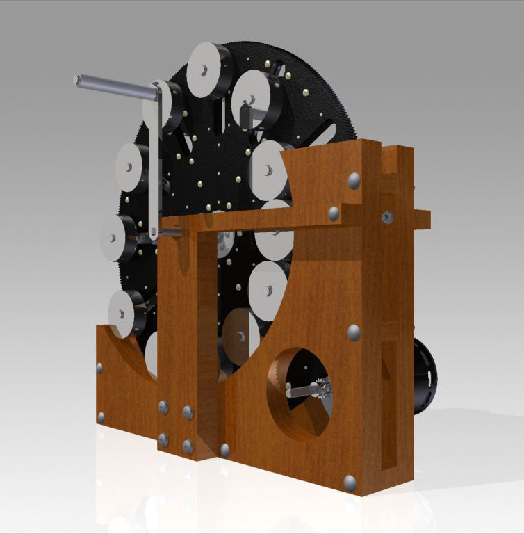
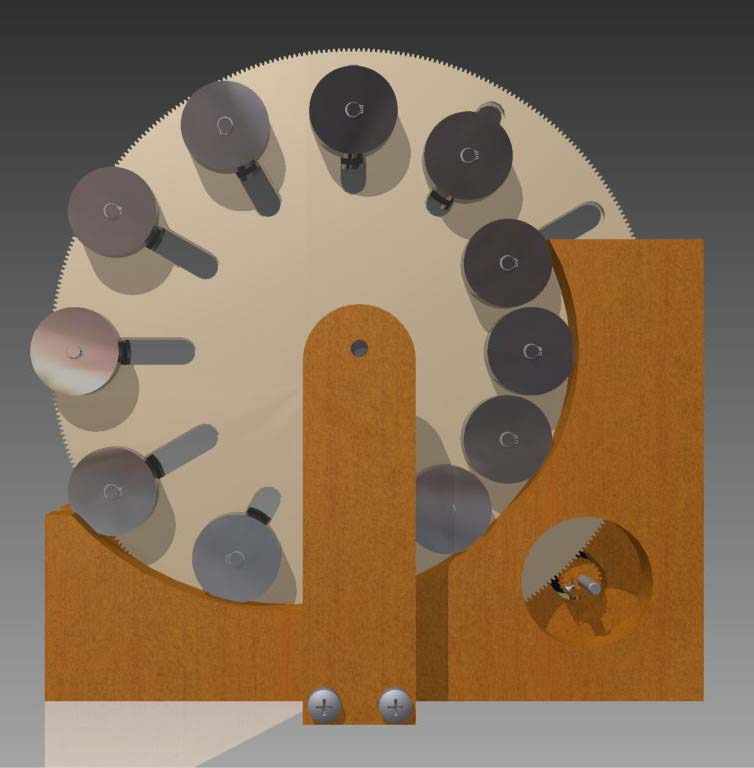
See below that I’ve now included a handle, so that the CCG Wheel can be brought up to speed manually.  It should only take about 60 to 80 rpm to prove it works or not, so the motor shouldn’t be needed for the initial testing.  
60 to 80 rpm is only a little over 1 rotation per second, which is possible to do by hand.
You’ll be able to FEEL, as you crank the handle, if the wheel is starting to ‘self-run’… And if it does ‘self-run’ you’ll be able to take your hand off the handle and it’ll keep going…

I’ve also extended the main wheel stand caps so they are bolted onto the CRs, to help compensate for the centrifugal force (of the weights pushing on the CRs) that will try to push the stands sideways by force through the axle. 

July 2015
Pictures (jpeg renders) of the version 9.3 Wheel.


Some of my conversation with the engineer who made the version 9.3 CAD drawings.  

June 2015
I’m currently getting the CCG Wheel engineered and CAD drawings made.  Here is a rendering of what we’ve done so far, version 9.3 of CCG Wheel:

Initial simple CAD drawing (best I could personally do with my personal TurboCAD)

PDF document to explain Version 9.2 of the CCG Wheel.

pdf of 9.2 CCG Wheel torque spreadsheet.  Sorry it’s spread out but you’ll get the idea.

Original Wiseman’s Wheels eBook.  Archived for posterity.

NapkinNotes to June 1, 2015.  Included so you can see my thinking as I developed these concepts.

Posted on Leave a comment

HEAT Technology Resources

DEFINITION OF CONCEPTS DEALING WITH HEAT

Knowledge of the effects and nature of heat is necessary for a clear understanding of H.E.A.T. Machine technology.  I have included this information for those who have no understanding of heat to have a reference point to study from and gather more information.  For those who know something of heat and its effects this will be a review.

Heat is a form of energy, and since it is not a substance, it can only be dealt with only through its effects on substances.  Every substance on earth contains some heat, so that when a body is “cold” it means only that the heat which it contains is less concentrated or less intense than the heat in some other body used for comparison.  One instructor told me, there is no such thing as cold, only a relative lack of heat.

Absolute zero:  As heat is removed from a substance its temperature decreases and there must be some point where there will be no more heat remaining in the substance to be extracted.  This point is known as absolute zero (-459.6oF) and has been determined only theoretically.

Measurement of heat:  In order to measure the heat in a substance, we must consider (1) the concentration of the heat and (2) the heat holding nature of the substance.  The white hot filament of an electric light bulb may contain fewer heat units than a pail of warm water, but in the filament the heat is more highly concentrated.  Temperature expresses the concentration of heat in a body, and this concentration is determined by measuring its effect on some other material which has been agreed upon as a standard of measurement.  Mercury thermometers are an example of a device in general acceptance.

Heat flow:  Heat flows from bodies of higher temperature to bodies of lower temperature in a manner similar to that in which water flows from a higher level to a lower level; and like water, it can be pumped uphill, from which point it can flow away in a different direction.  When two substances are brought into thermal contact (so heat can flow) the heat starts to flow from one into the other till their temperatures are equal, at which time the flow stops.  The greater the temperature difference between the two bodies, the faster the heat flow; and as the temperature difference approaches zero, the rate of heat flow approaches zero.  Heat can flow from one substance to another in three ways, or a combination of these. 

(1) Radiation:  In radiation, as from the sun, in which no material substance acts as a carrier, radiant heat may pass through a transparent substance without warming it and is stopped or absorbed only by an opaque substance.  Usually darker objects will absorb more heat than lighter ones.  Like light, radiant heat travels in a straight line from its source and can best be reflected with a polished surface.  For this reason, areas that you don’t want to absorb radiant heat should be surfaced with light colored reflective surfaces.

(2) Conduction:  In conduction, as through a bar or tube from one end to the other, the heat is passes from one particle of material to the next one touching it.  The flow of heat by conduction also takes place on the surface of the object to a liquid or gas touching it.

(3) Convection:  Convection is the transfer of heat from a warm body to a cold one by a fluid (liquid or gas) acting as a carrier between the two.  In natural convection the fluid usually absorbs heat by conduction, when fluids absorb heat they become lighter and rise (up against gravity).  The extra heat is usually given to some other “cooler” medium and the carrier fluid becomes heavy again, dropping down to be heated again.  In mechanical convection, the working medium is pumped form the warm to cold bodies and back again.  In any convection system, care must be taken to design for the most direct route.

Unit of heat:  The “amount of heat” added to, or subtracted from, a body can be measured best by the rise and fall in the temperature of a known weight of a substance.  As a standard for all heat measurement, the unit of heat has been agreed upon to be 1/180 part of the heat required to raise the temperature of 1 pound of water from 32oF to 212oF at atmospheric pressure.  This amount of heat is known as the British thermal unit, or BTU.

Specific heat:  The specific heat of a substance is the ratio of the heat required to raise the temperature of a unit weight of the substance 1o to the heat required to raise the temperature of water 1o at some specified temperature.  The specific heat is thus numerically equal to the number of BTU’s required to raise the temperature of one pound of the substance through 1oF.  The specific heat of water is 1 by adoption as standard and the specific heat of another substance (solid, liquid or gas) is determined experimentally by comparing it with water.  Specific heat expresses the heat holding nature of a substance compared to the heat holding capability of water.

Sensible heat:  Heat added to (or subtracted from) a substance without causing a change in state will cause an increase (or decrease) in temperature that can be measured with a thermometer.

Latent heat:  This is heat added (or subtracted) from a substance that can’t be measured with a thermometer.  This is the heat required for a substance to “change its state” at its freezing or boiling point.  If it is at its freezing point, it is called the latent heat of fusion.  If it is at its boiling point, and is going from a liquid to a gas, it is called its latent heat of vaporization.  If it is at its boiling point, and is going from a gas to a liquid, it is sometimes called its latent heat of condensation. 

A solid won’t get hotter than its freezing point no matter how much heat is applied, it will simply thaw faster.  The resulting liquid can then continue to rise in temperature with “sensible heat”.

Increasing the pressure on a substance will raise its freezing or boiling temperature but will not affect its latent heat of fusion or evaporation.

Decreasing the pressure on a substance will lower its freezing or boiling temperature but will not affect its latent heat of fusion or evaporation.

The latent heat of fusion of water at 32oF at atmospheric pressure is 144 BTU per pound (freezing or melting) 

The latent heat of vaporization of water at 212oF at atmospheric pressure is 970.3 BTU per pound (condensing or evaporating).

Total heat:  Since measurements of the total heat in a certain weight of a substance cannot be started at absolute zero, a temperature is adopted at which it is assumed there is no heat and tables of data are constructed on that basis for practical use.  Data tables giving the heat content of most commonly used refrigerants start at -40oF below zero as the assumed point of no heat;  tables for water and steam start at 32oF above zero.  Data tables usually show a notation showing the starting point for heat content measurement.

Insulation:  There would be no way for refrigeration systems to work if insulation was not applied to enclose the area being cooled.  Insulation should be applied that effectively reduces heat transfer to your cooled area by radiation, conduction and convection.

Refrigerants:  A liquid has different boiling temperatures (points) for different pressures under which is confined.  The boiling point is also the condensation point for that pressure.  This pressure-temperature relation must be determined experimentally for each liquid.

Water boils at 212oF at atmospheric pressure (14.7 psi absolute or zero psi gauge).  Water boils at 100oF at 28 inches of vacuum, Hg (.98 psi absolute) and at 338oF at 100 psi (gauge)

Because most liquids used as refrigerants have low boiling points, they can not exist as liquids at ordinary atmospheric temperatures and pressures.  They are held as liquids by confining them under higher pressures. 

Usually if refrigerant liquids are simply confined in a container, at atmospheric temperature, some of the liquid will turn to vapor, thus pressurizing the container enough that the rest of the liquid will stay in the liquid state.  If outside temperatures go up, a little more of the liquid will vaporize and the container’s interior pressure will rise again to maintain the rest of the liquid as liquid.  If outside temperatures go down, container pressures drop as it losses heat.

So cooling the container is a good way to reduce pressure and/or cause the gasses to lose their latent heat of vaporization and condense.

Critical temperature:  The temperature beyond which a liquid can no longer exist as a liquid, no matter how much pressure is applied.

Critical pressure:  The maximum pressure that can be applied to a liquid to prevent it from changing into a gas. 

Beyond the critical temperature and pressure point of a liquid, it will turn into a gas.  If you don’t have a container strong enough to hold the pressure resulting in the sudden expansion of liquid to gas in an enclosed area, then your container will explode.

My brother and I learned this the hard way.  Interestingly enough, it was on the exact same day the space shuttle Challenger blew up.

Saturated Refrigerant:  When the temperature of a liquid is raised to the boiling point corresponding with its pressure, both liquid and gas exist together and the condition is called saturated.  Below the boiling point it is only liquid.  Above the boiling point it is only gas and becomes what is called superheated gas.

Strictly speaking, saturated gas is “vapor” until it is superheated and then it is a gas.

Evaporator:  The evaporator provides contact for the refrigerant gasses and the area (substance) to be cooled.  Liquid refrigerant in the evaporator is maintained at a low enough pressure that it is well below its boiling point for the temperature of the substance to be cooled.  As the liquid refrigerant boils, it soaks up large amounts of latent heat.

In my H.E.A.T. Machine technology the evaporator is or is incorporated into my boiler.

Compressor:  In order to remove the “hot” (boiled) gasses from the evaporator, ordinary refrigeration systems use a compressor.  When the “hot” gasses are compressed, they rise in temperature according to Boyles Law.  They also rise in pressure, which raises the boiling point, so the gasses don’t have to lose as much temperature before they will condense.

Condenser:  The condenser is the heat exchanger that allows the heat from the compressed “hot” gasses to leave the refrigerant and go out into the surrounding (cooler) environment, like your kitchen.  That would be an air cooled condenser.  You can cool condensers with liquid or solids as well.

In my H.E.A.T. Machine technology, there is no condenser as such; the gasses have the heat taken out of them by doing mechanical work.

The condensed refrigerant drains (or is pumped) from the condenser into a storage reservoir where it waits its next chance at the evaporator.

Expansion valve:  Sometimes is a simple orifice, the expansion device allows only enough refrigerant into the evaporator for what the compressor removes, thus keeping the maximum boiling action going on.  At least until the cooling system has done its job.

Generally speaking, my H.E.A.T. Machine technology replaces the expansion valve with a turbine.  There is a company called Creative Energy Systems, in Edmonton, Alberta, Canada, that uses this concept to advantage.  They recognized that the pressure reducing valves on high pressure gas pipelines could be replaced with turbines.  In this manner they get the pressure drop (across the turbine) required to operate their appliances and recover some of the energy that was expended in pressureizing the gas.  This works because the turbine converts the heat energy in the gas to mechanical energy.  The result is a cooler gas coming out of the turbine.  The cooler gas has less volume, therefor less pressure.

In order to understand the H.E.A.T. Machine, you will also have to understand what is known as the GAS LAWS.  I will give you a preview here so you can look them up in your physics books to more completely understand them.  For example terms like “atmosphere”, “mole”, and “oK”.  They are not hard but you need a gut feeling for them or you may not understand some of the H.E.A.T. Machine design concepts.  You will also want to get familier with various conversion tables because data that you find may be metric.

Perfect Gas Law:  PV = nRT

P = Pressure in atmospheres

V = Volume in liters

n = number of moles

R = Gas constant (0.0821 liter-atmospheres/oK/mole.

T = Temperature in degrees K

If constant pressure,    V1/V2 = T1/T2

If constant temperature,           P1/P2 = V2/V1

If constant volume,       P1/P2 = T1/T2

Of course in real life nothing is constant, so the real answer usually involves a combination of the above.

Boyle’s Law:

If temperature is kept constant, the volume of a given mass of gas (mole) is inversely proportional to the pressure which is exerted upon it.

Initial Pressure   =        Pressure Change

Initial Volume               Volume Change

Charles’s Law:

If pressure is kept constant, the volume of a given mass of gas is inversely proportional to the pressure which is exerted upon it.

InitiaI Volume     =        Volume Change

Initial Temp. oK                        Final Temp. oK

There are more Gas Laws but these are the most applicable.

Work is defined as a force moving through a distance.  One foot-pound (ft-lb) is one pound moving through a distance of one foot.

Heat is the energy that is transfered between two regions because of a difference in their temperatures.

Bibliography

American Society of Refrigerating and Air Conditioning Engineers (ASRAE) Refrigerating fluid Charts and Tables, University of Idaho, Moscow, Idaho.

Modern Refrigeration and Air Conditioning, by Althouse / Turnquist / Bracciano, copyright 1992.  Published by The Goodhart-Willcox Company, Inc., South Holland, Illinois.

Heat Engines, Thermodynamics in Theory and Practice, by John F. Sandfort, Published by Anchor Books, Doubleday &Co. Inc., Garden City, New York, copyright 1962.

How to Make Home Electricity From Wind, Water and Sunshine,  By John A Kuecken.  Published by TAB Books Inc., Blue Ridge Summit, PA, 17214.  Copyright 1979.

Theory and Tests of Two-Phase Turbines, by David G. Elliott.  Prepared for the US Dept. of Energy through an agreement with NASA by Jet Propulsion Laboratory, California Institute of Technology, Pasadena, CA.  March 15, 1982.  JPL Publication 81-105.  

DOE/ER-10614-1, distribution category UC-66d, UC-93.

Boundary-Layer Breakthrough, The Bladeless Turbine, Volume II. Tesla technology Series, compiled by Jeffery A. Hayes.  Published by High Energy Enterprises, Inc., PO Box 5636, Security, Colorado, 80931.

Tesla’s Engine, A New Dimension For Power, compiled by Jeffery A Hayes.  Published by Tesla Engine Builders Association (TEBA), 5464 N. Port Washington Road, Suite 293, Milwaukee, Wisconsin, 53217.

How To Obtain Abundant Clean Energy, by Linda Baine McGown.  California State University, Long Beach, California and John O’M. Bockris, Texas A &M, Collage Station, Texas.  Plenum Press, New York and London, 227 West 17th Street, New York, NY, 10011.  Copyright 1980.

The Problem of Increasing Human Energy, with special reference to harnessing of the sun’s energy, by Nikola Tesla.  Originally published in Century Illustrated Monthly Magazine, June 1900.  Republished as Volume I. The Tesla Technology Series, with introduction by Jeffery A. Hayes and Steven R. Elswick by High Energy Enterprises, Inc., PO Box 5636, Security, Colorado, 80931.

Tesla, Man Out of Time, by Margaret Cheney.  Copyright 1981.  Published by Prentice-Hall, Inc.  Englewood Cliffs, NJ, 07632.

The Solar Electric Home, a photovoltaics how-to handbook, by Joel Davidson and Richard Komp.  Copyright 1983, published by Aatec Publications, PO Box 7119, Ann Arbor, Michigan, 48107.

Electronic Design and Construction of Alternate Energy Projects, by R. Andrews Motes, copyright 1985.  Published by TAB Books Inc., Blue Ridge Summit, PA, 17214.

The Sun, Second Edition, our Future Energy Source, by David K. McDaniels, University of Oregon, copyright 1984.  Reprint, published by Kriger Publishing Company, Malabar, Florida, 1991.

Our Future Motive Power, by Nikola Tesla.  Pages 230 to 236, Everyday Science and Mechanics, December 1931.

Solar Technology and Energy for Vital Economic Needs, The S.T.E.V.E.N. Foundation, 414 Triphammer Road, Ithaca, New York, 14850.  Professor Vanek.

The Alternative, by Dennis Lee.  A 150 page book and set of three video tapes available from Better World Technologies, PO Box 447, Vernon, New Jersey, 07462.

Borderland Sciences Research Foundation, PO Box 429, Garberville, CA, 95542.  Attn; Peter Lindemann.

I wish to extend a special thanks to the International Tesla Society for having me as a guest speaker and for all the little ways they support alternative energy technology, particularly technology that applies the work of Nikola Tesla.

The International Tesla Society has now been disbanded.