I can’t yet say. There are too many variables.
For example: the efficiency of the electrolyzer. For any given fuel volume there will be an optimum volume of BG to use as a combustion enhancement catalyst. I have found (see HyZor Technology book) that a law of diminishing returns applies. So for the first amp of BG production (on any given electrolyzer) you get the most gains. The next amp gets less gains, etc. until peak (peak varies with engine and electrolyzer efficiency), and then additional amperage actually LOSES mileage. A lot of people are in that range, not getting optimum gains, because they are assuming that if a little BG is good, a lot is better; and it’s not PRACTICALLY true.
The answer is somewhere in a balance of amperage (thus BG production) and the efficiencies with which BG is produced and used.
Note: I idled a 140ci engine TOTALLY on BG at a rate of 3000 liters/hour (see BG video 2). My average electrolyzer efficiency at the time was 3 watthours/liter, so I was using 9 kWh (from the Grid) to idle an engine for an hour in my shop. (It ran amazingly smoothly) I think if I had made ignition timing adjustments and raised the compression of the engine, I could have significantly reduced the BG consumption.
My point is that we are dealing with two different philosophies and which we concentrate on is totally dependent on electrolyzer efficiency.
The first philosophy is using BG as catalytic combustion enhancement.
As long as the electrolyzer can’t make enough BG to actually run the engine (when powered by the engine) then catalytic combustion enhancement of your fossil fuel is the ONLY practical avenue. Here is proof that BG assists carbon-fuel combustion, download PDF here.
Efficiency is the key here, because actual fuel mileage gains seriously depend on the electrolyzer efficiency. It takes a LOT of fuel to make electricity (most people have NO idea how much).
Here’s an example; part 1: Assuming the gasoline engine is 25% efficient, the alternator belt drive 90%, the alternator 55%, electrolyzer 60% (overall efficiency of energy conversion is 100*0.25*0.9*0.55*0.60 = 7.4%); then for each watt of electricity produced by the alternator took (100/7.4) 13.5 watts of fuel. The resulting BG needs to increase overall engine efficiency by 13.5 watts for every watt of BG produced before there will be ANY gain in fuel mileage.
So if we look at our efficiency bell curve, it will peak (for these conditions) when the overall engine efficiency does NOT increase by more than 13.5 watts of fuel per watt of BG produced.
Example part 2: Assuming we change NO other efficiencies in the engine (I definitely recommend making every efficiency upgrade possible but for our example we’ll hold to one variable) and ‘just’ increase the efficiency of the electrolyzer to 100% (which we have done and may be doing better). So the engine is 25% efficient, the alternator belt drive 90%, the alternator 55%, electrolyzer 100% (overall efficiency of energy conversion is 100*0.25*0.9*0.55*1 = 12.4%); then for each watt of electricity produced by the alternator took (100/12.4) 8 watts of fuel. The resulting BG needs to increase overall engine efficiency by 8 watts for every watt of BG produced before there will be ANY gain in fuel mileage.
So if we look at our efficiency bell curve (see the HyZor Technology Book), it will peak (for these conditions) when the overall engine efficiency does NOT increase by more than 8 watts of fuel per watt of BG produced.
Electrolyzer efficiency significantly affects how much BG is ‘optimum’, in a ‘feedback’ kind of loop. As the overall engine efficiency increases, the amount of fuel required to produce a watt of BG goes down (engine efficiency rises) further reducing the wattage of fuel needed to produce the BG.
Example part 3: So the engine is now 30% efficient, the alternator belt drive 90%, the alternator 55%, electrolyzer 100% (overall efficiency of energy conversion is 100*0.30*0.9*0.55*1 = 14.9%); then for each watt of electricity produced by the alternator took (100/14.9) 6.7 watts of fuel. The resulting BG needs to increase overall engine efficiency by 6.7 watts for every watt of BG produced before there will be ANY gain in fuel mileage.
So if we look at our efficiency bell curve, it will peak (for these conditions) when the overall engine efficiency does NOT increase by more than 6.7 watts of fuel per watt of BG produced.
Each efficiency gain, wherever applied, affects the entire system in a dynamic balance; which is one of the reasons I can’t answer the question: “1. How much BG does any given engine need or can effectively and efficiently use per liter of engine displacement.” The answer depends on several variables, which change with every application.
My rule of thumb, with my HyZors, is1 amp of BG for each liter of engine displacement.
This recommendation is based on:
1. The average ‘reserve capacity’ of most alternator systems (about 3 amps per liter of engine displacement). Greater amperage draw than this (for the HyZor) starts to create issues with the ability of the charging system to keep a battery fully charged (particularly in winter with short vehicle runs) and I have to assume that the electrolyzer isn’t the only ‘after-market’ load on the alternator.
2. Absolutely keeping the customer’s gains on the ‘most gains’ side of the efficiency bell curve. The first few amps gives the greatest gain. So typically, my HyZors are getting the same gains that found by other designs that use 10x the amperage.
3. As we increase electrolyzer efficiency, the volume of BG per amp rises, which will further increase customer’s fuel mileage without causing excessive stress on the charging system.
In the end, I want to make it possible for the customer to make informed choice about how much BG to produce, with the ability to vary the production to desire.
More reasons I can’t give an actual ‘volume of BG’ in any given application include:
Amps make Brown’s Gas (BG). There is traditionally a direct relationship of amps to gas production in an electrolyzer, EXCEPT with making BG. When making BG there’s also Electrically Expanded Water (ExW) produced, so there’s an additional gas volume (that extra gas makes BG electrolysis seem over-unity according to Faraday equations).
Gas production (volume of gas) is hard to measure correctly without very expensive equipment, so I give people an ‘amperage’ rule of thumb; which is accurate for MY electrolyzers only!
Generally the amperage and thus BG production (in my electrolyzers) should be about 1 amp per liter of engine displacement.
Gas production will vary depending on the electrolyzer design (more or less ExW), which is another reason I hesitate to give actual gas volume as a ‘rule of thumb’.
The more ExW you can produce (as a percentage of the BG), the less gas (BG) volume you need to get your mileage gains.
The ‘magic’ is in the ExW, not the hydrogen (H2). So if you have an electrolyzer that produces a larger quantity of ExW, then you do not need as much gas volume (and thus use less amperage) to get your optimum gains. My electrolyzers get the same gains as ‘others’ that use 10x the amperage.
Some engines will require more amperage for optimum fuel savings, some less. My 1983 Honda Civic Hatchback with 1.5 liter engine gets it’s best gain using only 0.95 amp.
The second philosophy of using BG is Water As Fuel.
This can only be possible when the electrolyzer efficiency is greater than 400% (this will allow an engine to ‘self-run’ on water).
It can only be practical if the electrolyzer efficiency is 4000% (this will allow the engine to have the excess power needed to be of practical use).
Since I know of no electrolyzer technology that is 4000% efficient, I choose to concentrate on the combustion enhancement philosophy discussed above.
Search Results for: hyzor
Q ~ Is a dry-cell more efficient?
… than a wet-cell? Not automatically.
Efficiency depends largely on the design of the electrolyzer, power supply, electrolyte, electrolyte density, electrolyte temperature, etc. These design parameters are largely independent of whether an electrolyzer is a ‘wet-cell’ or a ‘dry-cell’.
Efficient designs are optimized for the application. There are far too many electrolyzer design variables to discuss them all and the ramifications of each here. However, if building electrolyzers, keep in mind:
General Efficiency Considerations:
1. Don’t assume that any particular electrolyte or concentration is the best. Test each electrolyte with various concentrations until you find the optimum for your electrolyzer design. The main two electrolytes are NaOH (sodium hydroxide) and KOH (potassium hydroxide). We prefer NaOH because in our electrolyzer designs NaOH is 30% more efficient than KOH.
2. Wide plates tend to be more efficient than tall ones. You need to remove the bubbles from the plates as fast as possible, because wherever there is a bubble, there is inactive plate area. That is the one advantage of the wire-wound design of the ‘jar’ cell from Water4Gas.
3. Electrolyzers tend to run more efficiently when hot (reduces electrolyte resistance). There will be an optimum temperature for any given electrolyzer, electrolyte and electrolyte density; it’s best to be able to control the temperature.
4. Because electrolyte lowers resistance when the temperature rises, you need to deal with an effect I call ‘amperage-runaway’. Learn about efficient ways to control amperage-runaway (see HyZor Technology book). MOST power supply designs ‘out there’ are using technologies we abandonded decades ago.
5. It’s VITAL to use an electrolyzer design that does not allow electricity to ‘bypass’ the plates.This was never an issue in the original Faraday cell designs because the electrolyzer was just ONE cell.But in the various ‘series-cell’ designs, it becomes an issue. If electricity bypasses the plates (through the electrolyte or electrolyte foam), then you lose gas production (and wattage efficiency). So you want to ‘force’ the electricity to go through the cell/plate/cell/plate, etc. by making that ‘path’ less resistance.Again, this consideration is specific to series-cells, it doesn’t matter if it’s ‘wet’ or ‘dry’ design.
Dry-cell specific Considerations:If you do use a ‘remote reservoir’, here are a couple of design tips to raise efficiency.
1. Designs with pumps tend to eliminate the ‘surging’ that happens in convection cells. Be sure to use a pump large enough to remove the bubbles from the cells ASAP. If this is done, excellent results can be achieved with narrow plate spacing. Of course this also means a larger reservoir, because the bubbles need to be removed from the fluid before re-entering the electrolyzer. Perhaps a vortex could help.
2. Design for even flow of electrolyte through all cells, unrestricted exit of the liquid/gas mixture from the top of the cell-pack (like these people did, click) to the reservoir and DO NOT allow the electrolyte from any cell to mix with any other cell’s electrolyte until the electrolyte is well away from the electrolyzer (to prevent electricity from bypassing cells).
Wet-cell Efficiency:
For the world’s most efficient and practical (as far as we know) electrolyzer designs, read our Brown’s Gas books 1 and 2, the HyZor Technology book and watch Brown’s Gas videos 2 and 3. Then ask us about Pressure Relief tubes, Gridplates and the Barbell neutralzone.
Our HyZor, as currently designed, could be considered to be a compact hybrid ‘wet/dry- cell’ wherein the bulk of the electrolyte is separate from the (dual) electrolyzers.
I have not yet seen a dry-cell or wet-cell that can match or exceed the efficiencies of our current HyZor design, which have achieved 20+ MMW.
Can Brown’s Gas replace natural gas or propane?
In theory yes, there are ways to do it; but we do NOT recommend it.
Brown’s Gas uses a lot of electricity to make.
BG requires special explosion-proof containers.
BG can’t be stored under high pressure (it will explode).
In addition, the BG flame in it’s pure form will melt through cooking pots in seconds, so you have to dilute it in various ways (reducing it’s efficiency).
You’re better off using the electricity to do the heating directly. And there are much better (safer and cheaper) options to ‘store’ energy.
However: Mixing BG with a carbon-fuel is a GREAT idea as the BG acts like a catalyst, allowing the carbon fuel to release more heat than it otherwise would.
Note: There are ‘rumors’ (patents and plans on the internet) that, using ‘catalytic materials’, a BG heater can be constructed that radiates large amounts of heat (using little electricity). I have not yet seen proof that this works.
FAQ: Using BG in a furnace?
Not directly, for three reasons:
1. Brown’s Gas should be considered to be an ‘electrical’ flame, not a BTU flame. It’s dominant energy is electrical, not thermal, in nature. Brown’s Gas does not efficiently heat air or water, such mediums dissipate the electrical energy with minimal temperature rise.
2. Brown’s Gas also burns MUCH faster than regular furnace gasses like natural gas or propane and would result in furnaces, designed for slower burning fuels, to explode.
3. BG takes more energy to make than you get back from it (burning it directly and alone as a fuel).
So NO… Brown’s Gas isn’t practical to use as a ‘stand alone’ fuel in regular gas furnaces.
NOTE:
BG is VERY inefficient to directly heat air and water.
There are people who use BG to heat another material (other than air or water directly). The BG seems to be able to heat some materials to hotter temperatures than if you ‘just’ used electricity, thus achieving ‘over-unity’ heating. I have NOT confirmed this effect myself, yet.
Two such possibilities are:
1. H-CAT example. BG heating a catalytic material.
https://www.youtube.com/watch?v=Bd_yrSldFWw
2. Lots of people try heating a secondary material (like copper or magnesium oxide) with Brown’s Gas, and then having that material heat the air or water (there’s even patents for this technique).
While this technique is more efficient at heating than the ‘bare’ flame, I have not yet seen any proof that this ‘Rube Goldberg’ and expensive technique is more efficient than simply putting the electricity (needed to make the Brown’s Gas anyway) directly into a simple, efficient and inexpensive off-the-shelf resistive element.
There are (scam?) plans on the internet that use BG (HHO) to heat copper pipes… YES, BG will heat copper pipes and a fan blowing through the pipes will blow the heat into the room; BUT does it really take only 300 watts of energy to make 6000 watts of heat? No one has yet proven that to me.
The EXCEPTION is that Brown’s Gas DOES act like a catalyst to increase the efficiency of hydrocarbon-fuel combustion. If you use Brown’s Gas IN ADDITION TO a hydrocarbon fuel, then good things happen.
We have been with using Brown’s Gas to increase the efficiency of internal combustion and then add water to compensate for the fuel mass that we have reduced (water replaces the volume of fuel normally used as the combustion ‘cooling’ fluid). We have the world’s best such technology and we describe it in our ‘Brown’s Gas‘, ‘HyZor Technology‘, ‘Water Injection‘ and ‘Super Gas Saver Secrets‘ books.
http://eagle-research.com/shop
The catalytic effect works at the molecular level, helping the fuel’s atomic bonds to break with less energy input. I call it ‘lowering the combustion self-propagating endothermic energy requirement’. Thus, when the fuel burns, the combustion requires less of the heat energy produced to keep the combustion happening. This allows (for the same fuel mass) more (exothermic) energy to be released as heat. The quantity of additional heat energy released is far greater than the energy we use to make the Brown’s Gas. Of course, less efficient technologies than ours have less gain.
Here is proof that BG assists carbon-fuel combustion, download PDF here:
http://www.eagle-research.com/cms/node/443
Note: The actual energy put in (to make Brown’s Gas) is 98% recovered in the combustion process; that’s another reason why the catalytic enhancement shows up as a significant ‘free energy‘ gain as heat.
Our research so far indicates that this catalytic effect is much more effective on long chain hydrocarbons. So Methane (and Compressed Natural Gas) has the least gain, Gasoline (Petrol) has a greater gain, Diesel has a very good gain (around 50%) and heavy oils (like the crude used to fuel ocean going ships) get the greatest gain (can replace up to 90% of fuel with water). Coal combustion is enhanced too. All this assumes, of course, proper implementation of the technology.
This data is based on our own internal combustion research and on data acquired from various other sources that add hydrogen to assist carbon-fuel combustion. Our research has been done at ratios from about 5,000:1 carbon-fuel:Brown’s Gas. It is true that higher concentrations of Brown’s Gas result in even more fuel savings, but there is an optimum ratio for any given application (we are still researching to find that ratio). After the volume of BG required for the catalytic effect is optimized, any additional BG results in mileage lost (in internal combustion applications) and reduction in combustion temperature (in external combustion applications).
Because we were initially researching with increasing the efficiency of internal combustion in mobile applications, we were limited in by the vehicle’s electrical input. Stationary applications are not so limited. Since the actual energy put in (to make Brown’s Gas) is recovered in the combustion process, and the electricity didn’t come at such a dear price as in vehicle applications (up to 14 watts of fuel burned to make 1 watt of BG), there is a much greater potential for profitable efficiency gains in stationary applications (where the electricity to make the BG comes from the Grid).
I’m able to replace 50% of my Natural Gas in my shop with Brown’s Gas and still retain all the original equipment. By measuring the temperature of the air coming out of the furnace, I find the actual heating value of the mixture is exactly the same as the original NG alone (even though, by volume, BG has only 1/3 the ‘BTU’ value of NG; about 10 BTU per liter for BG and 30 BTU per liter for NG). Putting in more BG than 50% changes the combustion flame too much and the gas becomes incompatible with the furnace (can cause explosions).
Because of the cost of my electricity, water and Natural Gas, BG costs me only 10% of the NG. Every liter of gas I replace with BG saves me 90% of the cost of the NG. My electricity is $0.06 per kilowatthour. Water is $2 per 18 liters (about 5 gallons). Our WaterTorches make 1860 liters of gas for every liter of water put into them. Our WaterTorches use less than 2 watthours to make each liter of gas.
http://www.eagle-research.com/cms/node/620
http://www.eagle-research.com/cms/node/109
I see absolutely no reason that the same setup couldn’t be used with propane. We simply plumb the BG (out from the WaterTorch) into the furnace-gas flow just before the furnace-gas burner shutoff switch (I also add a special bubbler (to prevent backfire and gather excess moisture), a check valve (to prevent furnace-gas from escaping if the BG is disconnected) and a shutoff valve (normal for any gas appliance)). The BG then mixes with the furnace-gas before it goes into the burner, both enhancing the combustion of the furnace-gas and partially replacing it.
The WaterTorch is easily set for producing an exact volume of gas, and the pressure will rise to just above the furnace-gas pressure (coming from the final stage regulator) automatically, so a precise balance (and ratio) of BG to furnace-gas is simple and automatic. The WaterTorch is slightly modified (easily done) for automatic shutoff when your furnace shuts off and for automatic water fill.
I’ve done it. It’s simple. I see no reason that would prevent anyone from doing it (besides perhaps officials getting concerned because they don’t know what’s happening safety wise and the utility might change your meter, thinking the old one went bad (they did that with mine). This next Winter I’ll have it in my home as well as my shop.
On the subject of safety. In every way, BG is safer than NG, or Propane. It is lighter than air, it simply cannot build up a combustible concentration in a room that has even the simplest ventilation (cracks allowing air to move). BG is produced on demand, there is no stored gas. Our WaterTorches (electrolyzers) are designed extremely strong, well able to contain any internal explosions, usually without damage.
Do I need a MAP Enhancer?
I have been led to believe that I NEED a MAP Sensor Enhancer.
If you have a MAP sensor then you NEED a MAP Sensor Enhancer if you want to optimize fuel economy.
Not only will a MAP Enhancer ‘correct’ for manifold air pressure loss if using a fuel saver like the HyCO 2A, it will help the computer correct ignition advance for fuel savers like the HyZor (BG or HHO addition).
I had read somewhere that a simple potentiometer needed to be place on the MAP sensor. I cannot find that document for all my trying and cannot remember where I saw it. My MAP sensor has 3 wires. One ground, one 5watt power and one that adjusts voltage based on vacuum. Which wire do I attach the potentiometer to?
It’ll be 5 Volt power (not 5 watt). That’s the Power Supply voltage. The ground is ground. The signal wire (varies voltage) is where you want to apply the potentiometer (usually about 15K ohms). You put the pot. in SERIES into the signal wire.
The MAP sensor is a variable resistor that REDUCES the voltage signal going to the ECU (via the signal wire) by increasing resistance as the vacuum increases (lower absolute pressure). Here’s an example chart:
http://injector-rehab.com/shop/mapsensor.html
Lower pressure (supposedly) means there is less air (and or lower engine demand for fuel) so the ECU cuts back on fuel (and retards the ignition timing) to compensate.
What this means to you is that you can ‘fool’ your ECU into reducing fuel by ‘modifying’ the voltage signal going to the ECU.
More resistance (in series) lowers the voltage, which lowers the fuel consumption.
So I recommend wiring your potentiometer so that clockwise LOWERS resistance (more fuel) and counter-clockwise INCREASES resistance (less fuel).
You can buy assembled MAP Enhancers on eBay for cheaper than you can buy the parts, unless you already have them laying about.
I haven’t seen anything (at Eagle-Research) about a MAP Sensor Enhancer.
I do not currently sell a MAP Enhancer because they are being sold on eBay for less than I can build them. Usually they are just a 15K variable resistor (for variable voltage MAP sensors).
I have a 1989 Ford F-150 4 X 4 with a 302 cu. in. engine. The MAP sensor on a Ford does not send a voltage signal back to the computer but a Digital Frequency Signal. You cannot measure a voltage drop on the signal wire. You can only measure a frequency change.
That’s correct.
The Frequency varies from 100 Hz to 156 Hz at my elevation. I guess it is up to 159 Hz at Sea Level. The way it works is, as the vacuum increases the frequency drops. It varies based upon how many inches of vacuum in the intake manifold. That frequency signal from the MAP Sensor is also calculated and factored in by the computer to regulate how much fuel it pumps through the fuel injectors.
That’s correct.
The truck only has one (1) Oxygen Sensor and I have purchased the kit here for that.
Thank you 🙂
Do I need the MAP Sensor Enhancer in addition to the EFIE?
Yes.
This other place is saying i need both and they have a special one for the Fords that have a digital frequency signal but I don’t think they are adjustable.Their info says they are “set and forget” as it was stated on their site. That doesn’t seem like the optimum solution to me.
It’s not. It should be adjustable so that you can balance gains and performance for your vehicle and application.
If I do NEED the MAP Sensor Enhancer is there a way I can send my own digital frequency signal down that line to the computer and bypass the sensor completely?
Yes you can, but it wouldn’t be wise. You’d lose the whole reason the MAP sensor exists, which is to optimize air:fuel ratio and ignition timing ‘on the fly’ and automatically. Best to use a ‘correction’ circuit.
Could I just use a low, VERY LOW frequency generator? That way I could dial in different frequency settings for different driving conditions and circumstances. Does anyone have an idea about how to make this work or if it would work?
It would even help if I could just somehow put a circuit in-line that would raise the frequency by 10 to 15 Hz or more if possible. Any ideas?
Actually you want to LOWER the frequency because you want the CPU to ‘see’ a higher vacuum (less pressure) and yes, I have designed such a circuit. You put a 15K resistor in the power line (positive feed) leading up to the (frequency based) MAP sensor. This lowers the voltage that the sensor is getting and slows down the output frequency. But this solution also lowers the MAP sensor output signal voltage which MAY, in some cases, cause the CPU to think that the MAP sensor is bad.
So you add a ‘voltage pullup’ P-channel MosFet to the circuit, wired thus:1. MosFet Source is connected to the positive wire going to the MAP Enhancer BEFORE the above resistor.2. Signal the MosFet gate with the MAP sensor output signal. 3. MosFet Drain then goes to the CPU (in place of the original MAP Sensor signal).I like this particular MosFet for this application.http://www.mouser.com/Search/Refine.aspx?Keyword=IRFD9014YEAH! problem solved, you now have a simple low cost solution for frequency based MAP sensors.
Float Switch Circuit Board

This circuit board is NOT sold with wiring instructions.
Full instructions are in the “HyZor Assembly and Operation Instructions” available in HyZor Basic Kit or in the HyZor Resources
(Purchase HyZor Resources access separately). HyZor Resources Access is automatically available with purchase of HyZor Basic Kit).
This circuit board was developed when it was discovered that:
1. Most people didn’t need the full functionality of the boards sold with the Version A & B HyZors.
2. Some people made at least one mistake when soldering the components onto the more complicated board.
3. Some people are making up their own kits and like having a nicely designed board.
4. Some people buy electrolyzers from manufacturers that don’t include liquid level protection in their electrolyzers.
So we made a simple board that is sold fully assembled and tested.
We now offer it separately from the HyZor Kit because lots of people are making up their own kits. It is also retrofittable to most of the on-board electrolyzers on the market, for those people who would like to have these features:
1. Liquid level monitoring:
It is very convenient to know when water needs to be added. Our circuit board has a (dimable) blue LED (included) that tells you when your electrolyzer is turned on; and a yellow LED (included) that tells you when your liquid level is low.
2. Electrolyzer shutoff control:
It is vital NOT to allow the electrolyzer to run out of water. What most on-board electrolyzer manufacturers don’t tell you is that if you run out of water, your electrolyzer will explode! Explosions happen when the liquid level is too low to conduct current and the electricity is forced to arc between the plates. This circuit board shuts off power to your electrolyzer when the liquid level is low.
You can also use this technology to return (our design of) EFIEs to OEM setting when your electrolyzer shuts off; see EFIE Resources. This prevents a ‘lean’ condition when your combustion enhancing technology is turned off; allowing your fuel system to return to it’s OEM settings until water is added to the electrolyzer.
WATER INJECTION
This book tells you how to supplement your fuel with water. Details how to design, build, install and operate a low cost, simple, effective ‘active’ water injection system.
This is one of the Water as Fuel technologies mentioned in Water as Fuel, Book 1.
• Increase Power and Mileage
• Remove Carbon
• Engine runs cooler
• Increases engine life
• Decrease NOx, CO, HC
This technology can be ‘stand alone’ but works very well in combination with the HyZor.
A Water Injection installation also requires the Carburetor Enhancer (for Carbureted vehicles) or the EFIE (for fuel injected vehicles), so that the fuel from the regular fuel system is reduced when adding water.
HYCO 2DT CANISTER (USA)
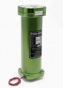
This HyCO 2DT unit is brand-named ‘Fuelizer’. They are CNC manufactured of aluminum using aircraft-quality standards. Made in USA.
The HyCO 2DT is a time proven, simple and practical fuel saver that is easily installed on turbocharged engines (diesel or gasoline).
Read all about it (even build your own HyCO 2DT) using our HyCO 2DT Manual.
On a Class 8 diesel truck, Government Standard independent testing showed the HyCO 2DT increased power about 14% while reducing fuel consumption about 10% (click).
Actual power gain and fuel saving depends on the vehicle and it’s operating conditions. Example: a Volkswagen Jetta increased fuel economy 40% when traveling over 70 miles per hour.
Many Class 8 trucks spend over $100,000 in fuel per year per truck (click). A guaranteed 10%+ fuel reduction would save over $10,000+ in the first year … often doubling the truck’s net income.
CALCULATE YOUR MONEY SAVINGS HERE (click)
Note: Using the PayPal Financing option below may allow you to pay for your HyCO 2DT with the money you are saving in fuel! PayPal financing is interest free if paid off in 6 months.
Other excellent HyCO 2DT applications are boats, ships and power plants.
Since the HyCO 2DT is turbocharger activated… engines that are idling, or any situation where the turbo is idle, do not get any benefit during that time. Vehicles that idle a lot, like city busses, are not a good application for HyCO 2DT technology. For those applications, see our Water as Fuel and HyZor Technology.
• The HyCO 2DT technology has been tested by major diesel engine manufacturers on their own dynos, and is being used, since 1990, by truck drivers all over the World.
• The HyCO 2DT does not void engine or vehicle warranties in North America (click)
• The HyCO 2DT is designed to prevent any possibility of engine damage. In fact, it helps engines run cleaner, cooler and longer.
• The HyCO 2DT requires near zero maintenance and no special attention from the driver. – Install and just drive normally.
• The HyCO 2DT does Not require any modifications or adjustments to the fuel system.
Older diesels don’t require any modification. Newer diesels may require Combustion Enhancement Interface Technology (CEIT); like EFIE or MAP Enhancer…
• The HyCO 2DT has now been used in trucks, boats and large stationary engines around the world for decades without a single known failure.
• The HyCO 2DT can be moved from engine to engine. As you upgrade, the new truck can be enhanced with the HyCO 2DT, or leave it on the old truck to get a better resale value (higher mileage truck).
•The HyCO 2DT does Not require any additional, ongoing ‘additives’ like tablets or ‘special’ fluids.
•The HyCO 2DT’s function is totally automatic. As you use more power your turbo pressure will rise, more pressure increases the volume of vapors from the HyCO 2DT. When you return to idle the turbo pressure stops and the HyCO 2DT stops creating the enhancing vapors.
• The HyCO 2DT, pays back your investment, in fuel savings, in less than 5 months (based on average truck fuel expenses) and is designed/built to last for decades with almost zero maintenance.
The HyCO 2DT is not the same device as the HyCO 2A system. The HyCO 2DT uses a different evaporation process and is designed specifically for engines with turbochargers.
Access privileges to the HyCO 2DT online Resources is included with this purchase.
For a limited time, this HyCO 2DT can qualify for rebates of up to $1,000 USD by participating in our Pre-Release/Rebate program.
– More information (click).
– More information (click).
For people who find the upfront cost of our fuel savers high for their budget, we now offer a financing option (through PayPal) that may allow you to literally pay for your fuel saving investment with your fuel savings!
Thus you can buy this product at literally NO COST higher than you are ALREADY paying NOW! Here is a fuel savings calculator to find what your fuel savings should be (click).
The financing is 6 equal monthly payments + a small finance fee.
To get the financing, just purchase the product using the PayPal option as you check out (you’ll need a PayPal account) and the financing option will automatically be presented to you during the normal checkout (payment) process.
After the technology is paid off, your fuel (and money) savings will continue! So from that point you’ll have ‘extra’ money in your pocket!
HYCO 2DT CANISTER (COLUMBIA)
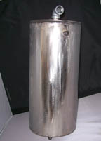
These HyCO 2DT units are, individually manufactured, using a steel container.
Made in Columbia.
The HyCO 2DT is a time proven, simple and practical fuel saver that is easily installed on turbocharged engines (diesel or gasoline).
Read all about it (even build your own HyCO 2DT) using our HyCO 2DT Manual.
On a Class 8 diesel truck, Government Standard independent testing showed the HyCO 2DT increased power about 14% while reducing fuel consumption about 10% (click).
Actual power gain and fuel saving depends on the vehicle and it’s operating conditions. Example: a Volkswagen Jetta increased fuel economy 40% when traveling over 70 miles per hour.
Many Class 8 trucks spend over $100,000 in fuel per year per truck (click). A guaranteed 10%+ fuel reduction would save over $10,000+ in the first year … often doubling the truck’s net income.
CALCULATE YOUR MONEY SAVINGS HERE (click)
Note: Using the PayPal Financing option below may allow you to pay for your HyCO 2DT with the money you are saving in fuel! PayPal financing is interest free if paid off in 6 months.
Other excellent HyCO 2DT applications are boats, ships and power plants.
Since the HyCO 2DT is turbocharger activated… engines that are idling, or any situation where the turbo is idle, do not get any benefit during that time. Vehicles that idle a lot, like city busses, are not a good application for HyCO 2DT technology. For those applications, see our Water as Fuel and HyZor Technology.
• The HyCO 2DT technology has been tested by major diesel engine manufacturers on their own dynos, and is being used, since 1990, by truck drivers all over the World.
• The HyCO 2DT does not void engine or vehicle warranties in North America (click)
• The HyCO 2DT is designed to prevent any possibility of engine damage. In fact, it helps engines run cleaner, cooler and longer.
• The HyCO 2DT requires near zero maintenance and no special attention from the driver. – Install and just drive normally.
• The HyCO 2DT does Not require any modifications or adjustments to the fuel system.
Older diesels don’t require any modification. Newer diesels may require Combustion Enhancement Interface Technology (CEIT); like EFIE or MAP Enhancer…
• The HyCO 2DT has now been used in trucks, boats and large stationary engines around the world for decades without a single known failure.
• The HyCO 2DT can be moved from engine to engine. As you upgrade, the new truck can be enhanced with the HyCO 2DT, or leave it on the old truck to get a better resale value (higher mileage truck).
•The HyCO 2DT does Not require any additional, ongoing ‘additives’ like tablets or ‘special’ fluids.
•The HyCO 2DT’s function is totally automatic. As you use more power your turbo pressure will rise, more pressure increases the volume of vapors from the HyCO 2DT. When you return to idle the turbo pressure stops and the HyCO 2DT stops creating the enhancing vapors.
• The HyCO 2DT, pays back your investment, in fuel savings, in less than 5 months (based on average truck fuel expenses) and is designed/built to last for decades with almost zero maintenance.
The HyCO 2DT is not the same device as the HyCO 2A system. The HyCO 2DT uses a different evaporation process and is designed specifically for engines with turbochargers.
Access privileges to the HyCO 2DT online Resources is included with this purchase.
For a limited time, this HyCO 2DT can qualify for rebates of up to $1,000 USD by participating in our Pre-Release/Rebate program.
– More information (click).
– More information (click).
For people who find the upfront cost of our fuel savers high for their budget, we now offer a financing option (through PayPal) that may allow you to literally pay for your fuel saving investment with your fuel savings!
Thus you can buy this product at literally NO COST higher than you are ALREADY paying NOW! Here is a fuel savings calculator to find what your fuel savings should be (click).
The financing is 6 equal monthly payments + a small finance fee.
To get the financing, just purchase the product using the PayPal option as you check out (you’ll need a PayPal account) and the financing option will automatically be presented to you during the normal checkout (payment) process.
After the technology is paid off, your fuel (and money) savings will continue! So from that point you’ll have ‘extra’ money in your pocket!
HYCO 2A MANUAL

Originally designed for carbureted engines. We have included information to adapt the technology to fuel injected vehicles.
The manual tells you how to build and operate the HyCO 2A system from scratch. Gains of 50% in fuel mileage are common.
All the HyCO systems are named that way because they are fuel evaporative systems; using air. Thus the name HydroCarbon (petro-fuels) Oxygenator (evaporate with air). The HyCO systems are simple and straightforward, designed to be fail-safe and to be built and installed by backyard mechanics.
. . . . . . . . . . . . . . . . . . . . . . . . . . . . . . . . . . . . . . . . . .
PLEASE NOTE:The HyCO 2A DVD is an assistant to this HyCO 2A Manual. It would not be possible to build the HyCO 2A using the DVD alone. The kit shown in the DVD is currently discontinued, because we presently don’t have the manpower to keep it in inventory. However, this Manual and the optional DVD show more than enough information to help you build your own.
We generally recommend the HyCO 2A over the HyZor because the HyCO 2A gets twice the gains that the HyZor does and is virtually maintenance free. The HyZor Technology is simpler to apply and it’s fun to tell people that you are using some Water as Fuel. (see chart)
Be sure to install a Carburetor Enhancer before applying any fuel saver on a carbureted vehicle.
Be sure to install appropriate MAP Enhancer and EFIEs before applying any fuel saver on a fuel injected vehicle.
HYCO 2A CANISTER PARTS (UNASSEMBLED)
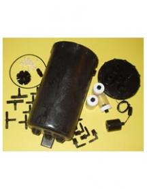
The HyCO 2A works on carbureted and fuel injected vehicles.
It currently gives double the gains of Water as Fuel technologies commonly referred to as on-board electrolyzers or HOD (including our world-class HyZor Technology).
The HyCO 2A kit (cold gasoline vapor system) is a time tested, reliable fuel saving technology that (when fully installed and properly adjusted) typically gets 50% mileage increase.
The HyCO 2A was put on-the-shelf when most vehicles on the market became fuel injected. It did not work well with fuel injection because it introduced a ‘vacuum leak’ into the intake manifold.
That problem was solved (embarrassingly not by us) with a simple 15K potentiometer you can pick up for a couple of dollars at Radio Shack. Or you can go online and search for “MAP enhancer” to buy one that someone else has made up all nice for you. The MAP sensor enhancer corrects (like the EFIE does for oxygen sensors) the signal coming from your MAP or MAF sensor, so that the vehicle’s computer doesn’t ‘see’ the vacuum leak and doesn’t add additional fuel.
When we were selling HyCO 2A kits, we only sold the container and the parts associated directly with it; these are the components that people would otherwise have to build themselves (the HyCO 2A Manual tells you how to build them yourself).
The rest of the components needed to complete the HyCO 2A system installation (wires, hoses, clamps, valves, etc.) are available at most automotive supply stores. The cost for the rest of the components varies depending on application, mostly being in the range of $70 to $150 dollars.
The HyCO 2A DVD and HyCO 2A Manual are now included with the purchase of any HyCO 2A Canister. However, HyCO 2A canisters won’t be available for the forseeable future. I’m just swamped with other projects and don’t have time to ‘re-start’ production of these very practical fuel savers. Anyone want to volenteer to be a manufacturer?
To complete a HyCO 2A installation, you do need:
For carbureted vehicles: a basic Carburetor Enhancer Kit,
For fuel injected vehicles: Appropriate EFIE(s) (from us) and a MAP Enhancer (buy elsewhere online).
The HyCO 2A Installation DVD (included), shows, step by step, how to assemble a HyCO 2A canister, install a basic HyCO 2A system and how to tune the HyCO 2A system to enhance your regular fuel system’s efficiency. It has been professionally done and is a real gem. Nothing like this has ever been sold in the ‘fuel saver’ world.
Mechanically inclined people tend to learn things by seeing it done, instead of reading. By both showing the entire concept and the project details, we make the entire assembly process simple to understand. We expect that this video will help achieve our goal of many more successfully completed HyCO 2A systems.
SKU ER1-K1-0008 • kit • 3.2341 lb / 1467 gm
For people who find the upfront cost of our fuel savers high for their budget, we now offer a financing option (through PayPal) that may allow you to literally pay for your fuel saving investment with your fuel savings!
Thus you can buy this product at literally NO COST higher than you are ALREADY paying NOW! Here is a fuel savings calculator to find what your fuel savings should be (click).
The financing is 6 equal monthly payments + a small finance fee.
To get the financing, just purchase the product using the PayPal option as you check out (you’ll need a PayPal account) and the financing option will automatically be presented to you during the normal checkout (payment) process.
After the technology is paid off, your fuel (and money) savings will continue! So from that point you’ll have ‘extra’ money in your pocket!